Avatar Technology - Best for Engineering

Avatar Technology is the Best Platform to run the topic about Engineering.and any other technical things to improve your skills.

Tuesday, August 4, 2020

Circuit Breaker

An electrical switch is an exchanging gadget that intrudes on the unusual or flaw flow. It is a mechanical gadget that upsets the progression of high size (flaw) current and in increases plays out the capacity of a switch. The electrical switch is primarily intended for shutting or opening of an electrical circuit, in this way shields the electrical framework from harm. 


Working Principle of Circuit Breaker 


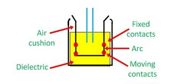
Electrical switch basically comprises of fixed and moving contacts. These contacts are contacting one another and conveying the current under ordinary conditions when the circuit is shut. At the point when the electrical switch is shut, the flow conveying contacts, called the terminals, connected each other under the weight of a spring. 


During the ordinary working condition, the arms of the electrical switch can be opened or shut for an exchanging and upkeep of the framework. To open the electrical switch, just a weight is required to be applied to a trigger. 


At whatever point a deficiency happens on any piece of the framework, the excursion loop of the breaker gets empowered and the moving contacts are getting separated from one another by some system, along these lines opening the circuit. 


classification of Circuit Breaker 

Circuit breakers are primarily ordered based on evaluated voltages. Circuit breakers underneath evaluated voltage of 1000V are known as the low voltage circuit breakers or more 1000V are known as the high voltage circuit breakers. 


The most broad method of the characterization of the electrical switch is based on the mechanism of circular segment termination. Such kinds of circuit breakers are as per the following 


👉Oil Circuit Breaker

👉Bulk Oil Circuit Breaker

👉Minimum Oil Circuit Breaker

👉Minimum Circuit Breaker

👉Air Blast Circuit Breaker

👉Sulphur Hexafluoride Circuit Breaker

👉Vacuum Circuit Breaker

👉Air Break Circuit Breaker


All high-voltage circuit breakers might be characterized under two primary classes i.e oil circuit breakers and oil-less electrical switch.

Monday, August 3, 2020

Single Line Diagram of Power System

Definition: Single line graph is the portrayal of a force framework utilizing the basic image for every part. The single line chart of a force framework is the system which shows the fundamental associations and game plan of the framework segments alongside their information, (for example, yield rating, voltage, opposition and reactance, and so forth.) 


It isn't important to show all the segments of the framework on a solitary line outline, e.g., electrical switch need not be appeared in the heap stream concentrate yet are the must for an assurance study. In the single line graph, the framework segment is normally attracted the type of their images. Generator and transformer associations, star, delta and impartial earthing are shown by images drawn by the side of the portrayal of these components. 


Circuit breakers are spoken to by rectangular squares. The figure appeared beneath speaks to the single line outline of a regular square framework. It is hard to adhere to a meaningful boundary outline of the couple of parts. So for improvement, the impedance graph is utilized for speaking to the force framework parts. 


Impedance Diagram for the Power System 


In impedance graph, every segment is spoken to by its proportional circuit, e.g., the simultaneous generator at the producing station by a voltage source in arrangement with the obstruction and reactance, the transformer by an ostensible ∏-proportionate circuit. The heap is thought to be detached and are spoken to by a resistive and inductive reactance in the arrangement. Nonpartisan earthing impedance doesn't show up in the chart as the fair condition is accepted. 


The chart appeared underneath is the decent 3-stage outline. It is likewise called positive grouping outline. Three separate outlines are additionally utilized for speaking to the positive, negative and zero grouping systems. The three separate impedance graphs are utilized in the short out for the investigations of unsymmetrical shortcoming. 


The impedance outline can additionally be disentangled by making certain suspicions and decreased to rearranged reactance. Reactance graph is drawn by dismissing the successful obstruction of generator armature, transformer winding opposition, transmission line opposition line charging and the polarizing circuit of transformers. Reactance graph of the force framework is demonstrated as follows. 


Reactance Diagram for the Power System 

The reactance outline gives an exact outcome for some force framework examines, for example, cut off, and so on. The winding opposition, including the line obstruction, are very little in examination with spillage reactance and shunt way which incorporates line charging and transformer polarizing circuit furnish an exceptionally high equal impedance with flaw 


It is viewed as that if the opposition is short of what 33% of the reactance, and obstruction is disregarded, at that point the blunder presented will be not more than 5 %. In the event that the opposition and reactance overlooked mistakes up to 12% might be presented. The mistakes mean their count gives a higher incentive than the real worth.


Electrical Earthing

Definition: The way toward moving the prompt release of the electrical vitality straightforwardly to the earth by the assistance of the low opposition wire is known as the electrical earthing. The electrical earthing is finished by interfacing the non-flow conveying some portion of the gear or nonpartisan of gracefully framework to the ground. 


For the most part, the excited iron is utilized for the earthing. The earthing gives the basic way to the spillage current. The short out current of the gear goes to the earth which has zero potential. In this manner, shields the framework and gear from harm. 


Kinds of Electrical Earthing 


The electrical hardware principally comprises of two non-flow conveying parts. These parts are nonpartisan of the framework or casing of the electrical gear. From the earthing of these two non-flow conveying portions of the electrical framework earthing can be ordered into two kinds. 


👉Nonpartisan Earthing 

👉Hardware Earthing. 

👉Nonpartisan Earthing 

In nonpartisan earthing, the impartial of the framework is straightforwardly associated with earth by the assistance of the GI wire. The impartial earthing is likewise called the framework earthing. Such sort of earthing is for the most part given to the framework which has star winding. For instance, the impartial earthing is given in the generator, transformer, engine and so forth. 

Hardware Earthing 

Such kind of earthing is given to the electrical gear. The non-current conveying some portion of the gear like their metallic edge is associated with the earth by the assistance of the leading wire. On the off chance that any shortcoming happens in the mechanical assembly, the short out current to pass the earth by the assistance of wire. Along these lines, shield the framework from harm. 

Significance of Earthing 

The earthing is fundamental due to the accompanying reasons 

The earthing shields the work force from the short out current. 

The earthing gives the most effortless way to the progression of short out current considerably after the disappointment of the protection. 

The earthing shields the contraption and staff from the high voltage floods and lightning release. 

Earthing should be possible by electrically associating the separate parts in the establishment to some arrangement of electrical conduits or anodes set close to the dirt or beneath the ground level. The earthing mat or cathode under the ground level have level iron riser through which all the non-current-conveying metallic pieces of the hardware are associated. 


At the point when the shortcoming happens the deficiency current from the gear moves through the earthing framework to the earth and in this manner shield the hardware from the flaw current. At the hour of the shortcoming, the earth tangle conductors ascend to the voltage which is equivalent to the obstruction of the earth tangle increased by a ground flaw. 


The reaching get together is called earthing. The metallic conveyors interfacing the pieces of the establishment with the earthing are called electrical association. The earthing and the earthing association together called the earthing framework.


Sunday, August 2, 2020

Voltage Source and Current Source

A Source is a gadget which changes over mechanical, compound, warm or some other type of vitality into electrical vitality. As such, the source is a functioning system component implied for producing electrical vitality. 


The different sorts of sources accessible in the electrical system are voltage source and flow sources. A voltage source has a compelling capacity of emf while the current source has a constraining capacity of current. 


Substance: 

👉Voltage Source 

👉Current Source 


The current and voltage sources are additionally classified as a perfect source or useful source. 


Voltage Source 


A voltage source is a two-terminal gadget whose voltage at any moment of time is consistent and is autonomous of the current drawn from it. Such a voltage source is called an Ideal Voltage Source and have zero inward opposition. 


For all intents and purposes a perfect voltage source can't be acquired. 


Sources having some measure of interior protections are known as Practical Voltage Source.due to this inner obstruction; voltage drop happens, and it makes the terminal voltage diminish. The littler is the inner opposition (r) of a voltage source, the more closer it is to an Ideal Source. 


The emblematic portrayal of the perfect and viable voltage source is demonstrated as follows. 


Figure An appeared beneath shows the circuit chart and qualities of a perfect voltage source: 


Figure B appeared beneath gives the circuit chart and attributes of Practical Voltage Source: 


The case of voltage sources is batteries and alternators. 


Current Source 


The current sources are additionally ordered as Ideal and Practical current source. 


A perfect current source is a two-terminal circuit component which supplies a similar current to any heap obstruction associated over its terminals. It is imperative to remember that the current provided by the current source is free of the voltage of source terminals. It has vast obstruction. 


A reasonable current source is spoken to as a perfect current source associated with the obstruction in equal. The emblematic portrayal is demonstrated as follows: 


Figure C demonstrated as follows, show its attributes. 


Figure D appeared beneath shows the attributes of Practical Current Source. 


The case of flow sources is photoelectric cells, authority flows of semiconductors.


AC Circuit

The circuit that is energized utilizing substituting source is called an AC Circuit. The rotating current (AC) is utilized for local and mechanical purposes. In an AC circuit, the estimation of the greatness and the bearing of current and voltages isn't consistent, it changes at an ordinary time period. 


It goes as a sinusoidal wave finishing one cycle as half positive and half negative cycle and is a component of time (t) or edge (θ=wt). 


In DC Circuit, the restriction to the progression of current is the main obstruction of the circuit while the restriction to the progression of current in the AC circuit is a direct result of opposition (R), Inductive Reactance (XL=2Ï€fL) and capacitive reactance (XC = 1/2 Ï€fC) of the circuit. 


In AC Circuit, the current and voltages are spoken to by extent and heading. The exchanging amount might possibly be in stage with one another relying on the different boundaries of the circuit like obstruction, inductance, and capacitance. The sinusoidal exchanging amounts are voltage and current which fluctuates as per the sine of edge θ. 


For the age of electric force, everywhere throughout the world the sinusoidal voltage and flow are chosen in light of the accompanying reasons are given beneath. 


👉The sinusoidal voltage and flow produce low iron and copper misfortunes in the transformer and pivoting electrical machines, which in turns improves the productivity of the AC machines. 

👉They offer less impedance to the close by correspondence framework. 

👉They produce less unsettling influence in the electrical circuit. 


Exchanging Voltage and Current in an AC Circuit 


The voltage that changes its extremity and greatness at normal time period is called an exchanging voltage. Thus, the heading of the current is changed and the greatness of current changes with time it is called rotating current. 


At the point when a substituting voltage source is associated over a heap obstruction as appeared in the figure beneath, the current through it streams a single way and afterward the other way when the extremity is switched. 


The waveform of the rotating voltage as for the time and the current coursing through the opposition (R) in the circuit is demonstrated as follows. 


There are different sorts of AC circuit, for example, AC circuit containing just obstruction (R), AC circuit containing just capacitance (C), AC circuit containing just inductance (L), the blend of RL Circuit, AC circuit containing opposition and capacitance (RC), AC circuit containing inductance and capacitance (LC) and obstruction inductance and capacitance (RLC) AC circuit. 


The different terms which are much of the time utilized in an AC circuit are as per the following 


Adequacy 

The most extreme positive or negative worth accomplished by a rotating amount in one complete cycle is called Amplitude or pinnacle worth or greatest worth. The most extreme estimation of voltage and current is spoken to by Em or Vm and Im individually. 


Shift 

One-half cycle is named as shift. A rotation length is of 180 degrees electrical. 


Cycle 

At the point when one lot of positive and negative qualities finishes by an exchanging amount or it experiences 360 degrees electrical, it is said to have one complete Cycle. 


Immediate Value 

The estimation of voltage or current at any moment of time is called an immediate worth. It is indicated by (I or e). 


Recurrence 

The quantity of cycles made every second by a substituting amount is called recurrence. It is estimated in cycle every second (c/s) or hertz (Hz) and is meant by (f). 


Timespan 

The time taken in seconds by a voltage or a current to finish one cycle is called Time Period. It is meant by (T). 


Wave Form 

The shape got by plotting the immediate estimations of a rotating amount, for example, voltage and current along the y-hub and the time (t) or edge (θ=wt) along the x-pivot is known as a waveform. 


This is about AC circuits.

Thursday, July 30, 2020

Shaded Pole Induction Motor

Definition: The concealed shaft enlistment engine is just a self-beginning single-stage acceptance engine whose one of the post is concealed by the copper ring. The copper ring is likewise called the concealed ring. This copper ring go about as an optional twisting for the engine. The concealed post engine turns just one specific way, and the converse development of the engine is unimaginable. 


Why the Shaded Pole Induction Motor structures for low force rating? 


The force misfortunes are high in the concealed post enlistment engine. What's more, the force factor of the engine is low. The beginning force actuates in the acceptance engine are likewise low. Due to the accompanying reasons the engine has helpless effectiveness. Subsequently, their plans are kept little, and the engine has low force appraisals. 


Development of Shaded Pole Induction Motor 


The concealed shaft engine may have two or four posts. Here in this article, we utilize the two shaft engine for effortlessness. The speed of the engine is conversely relative to the quantity of shafts utilized in the engine. 


Stator – The stator of the concealed post engine has a notable shaft. The notable shaft implies the posts of the magnet are anticipated towards the armature of the engine. Each shaft of the engine is energized by its energizing curl. The copper rings conceal the circles. The circles are known as the concealing loop. 


The posts of the engine are overlaid. The overlay implies different layers of material are utilized for making the shafts. Along these lines, that the quality of the shaft increments. 


The space is developed at some separation separated from the edge of the shafts. The shortcircuited copper curl is set in this opening. The part which is secured with the copper ring is known as the concealed part and which are not secured by the rings are called unshaded part. 


Rotor – The concealed shaft engine utilizes the squirrel confine rotor. The bars of the rotor is slanted at a point of 60º. The slant should be possible for getting the better beginning force. 


The development of the engine is exceptionally straightforward in light of the fact that it doesn't contain any commutator, brushes, gatherer rings, and so on or some other part. The concealed shaft acceptance engine doesn't have any outward switch. Along these lines, the odds of disappointment of the engine are less. 


The outward switch is the sort of electrical switch that starts working by utilizing the divergent power, produced by the pivoting shaft. It is additionally utilized for controlling the speed of the pole. 


shaded Pole Induction Motor Working 


At the point when the flexibly is associated with the windings of the rotor, the substituting transition instigates in the center of the rotor. The little part of the motion connect with the concealed loop of the engine as in light of the fact that it is shortcircuited. The variety in the transition prompts the voltage inside the ring in view of which the flowing current incites in it. 


The coursing current builds up the transition in the ring which restricts the primary motion of the engine. The transition initiates in the concealed part of the engine, i.e., an and the unshaded segment of the engine, i.e., b have a stage contrast. The fundamental engine transition and the concealed ring motion are additionally having a space dislodging by a point of 90°. 


The association chart of the Shaded Pole Motor is demonstrated as follows. 


As there is existence relocation between the two transitions, the turning attractive field actuates in the curl. The pivoting attractive field builds up the beginning force in the engine. The field pivots from the unshaded segment to the concealed part of the engine. 


Uses of the Shaded Pole Induction Motor 


The different uses of the Shaded Poles Motor are as per the following:- 

  • They are appropriate for little gadgets like transfers and fans in light of its minimal effort and simple beginning. 

  • Utilized in exhaust fans, hair dryers and furthermore in table fans. 

  • Utilized in cooling and refrigeration gear and cooling fans. 

  • Phonographs, recording devices, projectors, copying machines. 

  • Utilized for beginning electronic tickers and single-stage simultaneous planning engines. 

  • This sort of engine is utilized to drive the gadgets which require low beginning force.


Compensation Theorem

Compensation Theoremexpresses that in a direct time-invariant system when the opposition (R) of an uncoupled branch, conveying a current (I), is changed by (ΔR), at that point the flows in all the branches would change and can be acquired by accepting that a perfect voltage wellspring of (VC) has been associated to such an extent that VC = I (ΔR) in arrangement with (R + ΔR) when every other source in the system are supplanted by their inside protections. 


In Compensation Theorem, the source voltage (VC) contradicts the first current. In straightforward words, remuneration hypothesis can be expressed as – the obstruction of any system can be supplanted by a voltage source, having a similar voltage as the voltage drop over the opposition which is supplanted.


Clarification 

Let us accept a heap RL be associated with a DC source arrange whose Thevenin's proportionate gives V0 as the Thevenin's voltage and RTH as the Thevenin's obstruction as appeared in the figure beneath: 


Here,


Let the heap opposition RL be changed to (RL + ΔRL). Since the remainder of the circuit stays unaltered, the Thevenin's proportional system continues as before as appeared in the circuit chart underneath: 


Here,


The change of current being termed as ΔI

Therefore,


Putting the estimation of I' and I from the condition (1) and (2) in the condition (3) we will get the accompanying condition: 


Presently, putting the estimation of I from the condition (1) in condition (4), we will get the accompanying condition: 


As we probably am aware, VC = I ΔRL and is known as remunerating voltage. 

Along these lines, condition (5) becomes,


Consequently, Compensation hypothesis tells that with the difference in branch opposition, branch flows changes and the change is proportional to a perfect remunerating voltage source in arrangement with the branch contradicting the first current, where every other source in the system being supplanted by their inward protections.


Wednesday, July 29, 2020

Applications of Induction Motor

The Polyphase Induction Motor is an engine whose stator contains various windings. They are more prominent than one torque or one kilowatt. The National Electrical Manufacturers Association (NEMA) has indicated the engines as per the different Class, which are talked about beneath in detail. There are different utilizations of Polyphase injury rotor acceptance engines, Polyphase confine enlistment engines. They are as per the following: 


Utilizations of Polyphase Wound Rotor Induction Motors 


Wound rotor engines are reasonable for loads requiring high beginning force and where a lower beginning current is required. 


The Wound rotor enlistment engines are likewise utilized for loads having high dormancy, which brings about higher vitality misfortunes. 


Utilized for the heaps which require a slow development of force. 


Utilized for the heaps that require speed control. 


The injury rotor enlistment engines are utilized in transports, cranes, siphons, lifts and blowers. 


The greatest force is over 200 percent of the full burden esteem while the full burden slip might be as low as 3 percent. The proficiency is around 90 %. 


Utilizations of Polyphase Cage Rotor Induction Motors 


Numerous polyphase confine enlistment engines are accessible in the market to fulfill the need of the few mechanical applications and different beginning and running condition necessity. They are ordered by the Class. 


The speed force qualities of Cage Induction Motor of different Classes are demonstrated as follows. 


Class A Motors 


Class An engines have typical beginning force, high beginning current and low working slip (0.005-0.015). The structure has low opposition single enclosure rotor. The productivity of the engine is high at full burden. Uses of Class An engines are fans, blowers, divergent siphons, and so forth. 


Class B Motors 


Class B engines have ordinary beginning force, low beginning current and low beginning current and low working slip. The engine is structured, in such an approach to withstand the high spillage reactance, therefore, the beginning current is diminished. The beginning force is kept up by utilization of a twofold enclosure or profound bar rotor. 


The Class B engines are most regularly utilized engine and utilized for full voltage beginning. The applications and the beginning force are same as that of Class An engines. 


Class C Motors 


The class C engines have high beginning force and low beginning current. Such engines are of the twofold pen and profound bar and has higher rotor opposition. The heaps are blowers, transports, responding siphons, smashers, and so forth. 


Class D Motors 


Class D engines have the most elevated beginning force when contrasted with the various class of engines. The bars of the rotor confine are comprised of metal. These sorts of engines have low beginning current and high working slip. The estimation of full burden working slip changes between 8 to 15%. In this way, the productivity of the engine is low. 


These engines are reasonable for driving discontinuous burdens which require visit speeding up and high loads. For instance – punch presses, pieces of machinery and kick the bucket stepping machines. At the point when the engine is driving the high effect loads, it is coupled to a flywheel to give active vitality.


Capacitor Start Induction Motor

A Capacitor Start Motors are a solitary stage Induction Motor that utilizes a capacitor in the helper twisting circuit to deliver a more prominent stage contrast between the current in the fundamental and the assistant windings. The name capacitor begins itself shows that the engine utilizes a capacitor with the end goal of the beginning. The figure underneath shows the association outline of a Capacitor Start Motor. 


Content: 

  • Phasor Diagram 

  • Qualities of the Capacitor Start Motor 

  • Utilizations of the Capacitor Start Motor 


The capacitor turn over engine has a pen rotor and has two windings on the stator. They are known as the principle winding and the assistant or the beginning winding. The two windings are set 90 degrees separated. A capacitor CS is associated in arrangement with the beginning winding. A radiating switch SC is additionally associated in the circuit. 


The Phasor Diagram of the Capacitor Start engine is demonstrated as follows. 


IM is the current in the fundamental winding which is slacking the assistant current IA by 90 degrees as appeared in the phasor outline above. Therefore, a solitary stage flexibly current is part into two stages. The two windings are uprooted separated by 90 degrees electrical, and their MMF's are equivalent in size yet 90 degrees separated in time stage. 


The engine goes about as a reasonable two-stage engine. As the engine moves toward its appraised speed, the helper winding and the beginning capacitor is disengaged consequently by the radial switch gave on the pole of the engine. 


Attributes of the Capacitor Start Motor 


The capacitor turns over engine builds up an a lot higher beginning force of around 3 to 4.5 occasions of the full burden force. To get a high beginning force, the two conditions are fundamental. They are as per the following:- 


The Starting capacitor esteem must be huge. 


The valve of the beginning winding opposition must be low. 


The electrolytic capacitors of the request for the 250 µF are utilized due to the high Var rating of the capacitor prerequisite. 


The Torque Speed Characteristic of the engine is demonstrated as follows. 


The trademark shows that the beginning force is high. The expense of this engine is more when contrasted with the split stage engine on account of the extra expense of the capacitor. The Capacitor turn over engine can be switched by first carrying the engine to rest condition and afterward turning around the associations of one of the windings. 


Uses of the Capacitor Start Motor 

The different uses of the engine are as per the following:- 

These engines are utilized for the heaps of higher inactivity where continuous beginning is required. 

Utilized in siphons and blowers 

Utilized in the cooler and climate control system blowers. 

They are additionally utilized for transports and machine instruments.

Capacitor Start Capacitor Run Motor

The Capacitor Run Motor Capacitor Start has a cage rotor, and its stator has two windings known as Main and Auxiliary Windings..The two windings are uprooted 90 degrees in space. There are two capacitors in this technique one is utilized at the hour of the beginning and is known as beginning capacitor. The other one is utilized for ceaseless running of the engine and is known as RUN capacitor. 


So this engine is named as Capacitor Start Capacitor Run Motor. This engine is otherwise called Two Value Capacitor Motor. Association graph of the Two valve Capacitor Motor is demonstrated as follows 


There are two capacitors in this engine spoke to by CS and CR. At the beginning, the two capacitors are associated in equal. The Capacitor Cs is the Starting capacitor is brief timeframe appraised. It is practically electrolytic. A lot of current id required to get the beginning force. Along these lines, the estimation of the capacitive reactance X ought to be low in the beginning winding. Since, XA = 1/2Ï€fCA, the estimation of the beginning capacitor ought to be huge. 


The appraised line current is littler than the beginning current at the typical working state of the engine. Subsequently, the estimation of the capacitive reactance ought to be enormous. Since, XR = 1/2Ï€fCR, the estimation of the run capacitor ought to be little 


As the engine arrives at the coordinated speed, the beginning capacitor Cs is separated from the circuit by a radial switch Sc. The capacitor CR is associated forever in the circuit and along these lines it is known as RUN Capacitor. The run capacitor is long time evaluated and is made of oil filled paper. 


The figure beneath shows the Phasor Diagram of the Capacitor Start Capacitor Run Motor.


Fig(a) shows the phasor chart when at the beginning both the capacitor are in the circuit and Ï• > 90⁰.


 Fig (b) shows the phasor when the beginning capacitor is detached, and Ï• gets equivalent to 90⁰. 


The Torque Speed Characteristic of a Two Value Capacitor Motor is demonstrated as follows. 


This kind of engine is tranquil and smooth running. They have higher proficiency than the engines that sudden spike in demand for the principle windings as it were. They are utilized for heaps of higher idleness requiring successive beginnings where the most extreme draw out force and proficiency required are higher. The Two Value Capacitor Motors are utilized in siphoning hardware, refrigeration, air blowers, and so forth.